slide
image

11 Thursday Sep 2025
Posted in Uncategorized
slide
image
16 Sunday Jul 2023
Posted in Golf, Uncategorized
Maximum error e of putter face angle from square at impact can be closely approximated by a much simpler formula versus the arctan formula. Maximum allowable error of putter face angle at impact:
e = 10/Length of Putt
e is the maximum allowable deviation from square of the putter face in degrees
Lenth of Putt is in feet
Table comparing the simple e =10/putt length in feet formula versus the e = arctan(2/put length in inches):
Lenth of putt in feet e=10/putt length in feet e=arctan(2/putt length)
5 feet putt: 2 degrees versus 2 degrees
10 feet putt: 1 degree versus 0.96 degree
15 feet putt: 0.66 degree versus 0.64 degree
20 feet putt: 0.50 degree versus 0.48 degree
25 feet putt: 0.40 degree versus 0.38 degree
30 feet putt: 0.33 degree versus 0.32
The above table shows that the simple formula of e=10/length is a very close approximation, as well as it provides more understandable results of 1 degree for 10 feet putt, half degree for 20 feet putt, and a third degree for 30 feet putt.
24 Wednesday Jun 2015
Tags
(Continued from Part 2)
It can be seen that a squared putter face at the moment of impact with the golf ball is of much more importance versus the path of the putter, as it seems that the path of the putter head is of little importance, as seen in Experiment #1 and #2.
In Experiment #1, the putter head path was good, but the putt missed because the putter face was off and not squared at impact. The ball basically took off in the direction where the putter face was pointing.
A good stroke path cannot fix a bad face angle.
In Experiment #2, the putter path was way off about 40 degrees to the right of the target line, but the putt was made because the putter face was squared at impact.
A good and squared putter face at impact can fix a bad putter stroke path.
The precise ratio of importance between clubface angle and clubhead path will be discussed later, as the ratio is different depending of the club from putter to the driver. For the putter, the ratio can be taken as 90 to 95 percent important for face angle versus only 5 to 10 percent important for the putter head stroke path. For the driver, the average ratio is 70 percent important for face angle versus 30 percent important for the driver swing path for an advanced player. (For the big slicer, driver swing path becomes up to 90 percent important versus driver face angle.)
A lot of work to get the putter face as squared as possible at ball impact to the start of the target line can increase the making of medium and long putts.
One method is the use of guide lines on the ball to help making putts. In the old days, the ball-name label imprinted on the ball can be used as the putting guide line. Now, a long line is drawn around the ball to serve as a long putting guide line, as seen on television broadcasts of PGA golf tournaments. Most times, the guide line, or ball-name label is set inline with the starting part of the target line.

Figure 3-1.
Figure 3-1 shows the ball-name label set inline with the initial part of the target line, so as to served as a guide line for the putting stroke. For a flat and straight putt, the ball-name guide line serves to point in the direction of the hole.
Less seen is to place the ball with the ball-name label squared to the start of the target line, as shown in Figure 3-2 below:

Figure 3-2.
In Figure 3-2 the ball-name label is set squared to the starting part of the target line. This set up of the ball-name guide line is to encourage returning the putter face to the same squareness as the ball-name at the moment of ball impact.
Because squareness of putter face at impact is ninety percent or more of importance, logic implies that the ball guide line be set squared to the target line as in Figure 3-2 for over ninety percent of putting practice to improve the squareness of clubface at impact with ten percent of practice with the ball-name label, or drawn guide line on the ball set inline with the target line to improve the stroke path.
From a previous blog, the theoretical allowable deviation of putter face from square at impact is calculated as the arctangent of golf hole radius divided by the length of the putt. For a short straight putt on flat and smooth surface, the putter face is to be no more than one degree off at impact. For a medium putt, less than half a degree deviation from square is allowed for making the putt. For long putts, less than one-third degree of deviation from square at impact is allowed. For very long putts, deviations of less than one-tenth, one-hundredth, and so forth may be called for, although it is probably beyond achievable to consistently maintain deviations from square to such tiny fractions of a degree. These precision is in the realm of surgeons who can cut off a single layer of cell tissues.
The are many systems to get the putter face as squared as possible at impact. Whole books may be written on this single topic. There is even mathematics that can be used to putt in “hyper-space” where in sci-fi movies, long distances of many light years can traveled as short distances in hyper-space. Putting in hyper-space can make 30 or more feet putts almost as easy as a two feet putt.
While putter stroke path is of much less importance, it can still decide whether a long putt is made or not. Here too many articles and books are available for increasing the precision of the putting stroke.
Before delving further into this topic, judging and controlling putting distance will be discussed in the next blogs.
24 Wednesday Jun 2015
Posted in Golf
Tags
(Continued from Part 1)
Experiment #2 – Putter Path Off, while Putter Face Good.
While the putter path is way off, the putter face angle is good and squared at impact, and the putt is made.

Figure 2-1.

Figure 2-2.
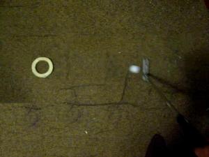
Figure 2-3.
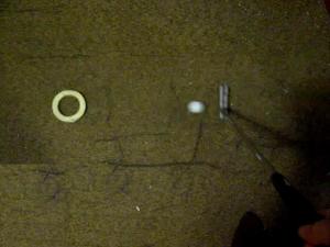
Figure 2-4.

Figure 2-5.
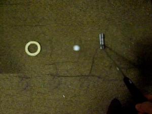
Figure 2-6.
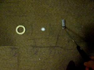
Figure 2-7.

Figure 2-8.

Figure 2-9.
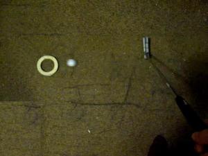
Figure 2-10.

Figure 2-11.

Figure 2-12.
Although the putter stroke path is almost forty-five degrees to the right of the hole, the putt was made, when the putter face was squared at the moment of impact with the ball.
(Continued in Part 3 …)
23 Tuesday Jun 2015
Posted in Golf
Tags
The relative importance of putter path versus putter face angle can be seem from the below two experiments. In the first experiment, the putter stroke path is straight towards the hole, while the putter face angle is off from being squared at impact. In the second experiment, which is shown in Part 2, the putter stroke path is way off from the hole, while the putter face angle is kept squared at impact.
Experiment #1 – Putter Path Good while Putter Face Off.
 Figure 1-1.

Figure 1-2.

Figure 1-3.
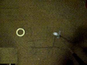
Figure 1-4.

Figure 1-5.

Figure 1-6.

Figure 1-7.

Figure 1-8.
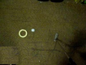
Figure 1-9.
Figure 1-10.

Figure 1-11.

Figure 1-12.

Figure 1-13.

Figure 1-14.
The above sequence of photos shows the putter stroke path is straight towards the hole, but the putter face angle at impact (Figure 1-4) is off pointing to the right of the hole. As a result, the ball takes off in the direction where the putter face is pointing at impact, rather than the ball traveling in the direction of the putter head stroke path.
A good putter stroke path is useless, if the putter face angle is poor at impact.
(Continued in Part 2 …)
30 Saturday May 2015
Posted in Science
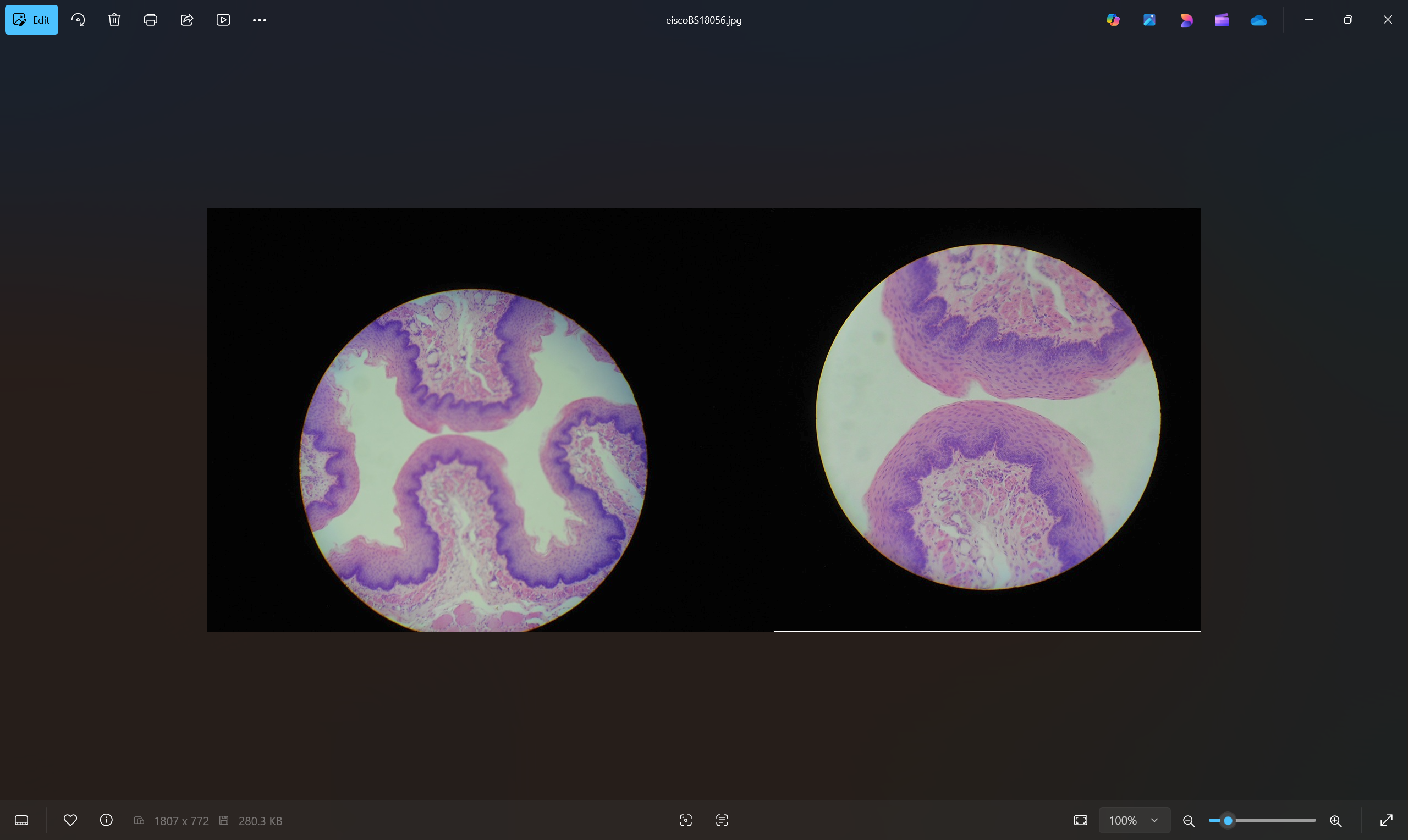
Spiral and Coiled Vein Structures in Plant Leaves, and Plant Fruits
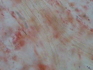
Abstract: Photographs taken through light microscopy illustrate the spiral and coiled tubular structure of plant leaf veins, and of veins in the meat of plant fruits. In the watercress leaf, the veins are flexible enough to be manually pulled out to a spring like shape. The main vein of the leaf is formed in a bundle of many spiral tubes. The spiral tubes in the bundle branch away one by one from the main bundle as they progress towards the tip of the leaf. The spiral tubes form two types with spirals closely, and sparsely spaced. The spiral tubes can form pointed frontal tips, which appear to be able to penetrate, and to attach to the sides of other veins. Besides leafs, the meat of watermelon exhibit similar spiral tubular veins.
Introduction: Pictures by light microscopy illustrate the spiral and coiled tubular structure of plant leaf veins, and of veins in the meat of plant fruits. Plant veins provide plumbing, and structure. They influence the developmental shapes of leaves. Leaf veins, and fruit veins exhibit spiral markings, which are similar to the coiled structure of slinky® toys, and coiled shaped flexible ducts for connecting inside room portable air conditioners to windows. In the watercress leaf, the veins of its leaf are flexible enough to be manually drawned out to a spring like shape. The main vein of the leaf is formed in a bundle of many spiral tubes. These spiral tubes in the bundle branch away one by one from the main bundle as they progress towards the tip of the leaf. The spiral tubes form two types with spirals closely, and sparsely spaced. The spiral tubes can form pointed frontal tips, which appear to be able to penetrate, and to attach to the sides of other veins. Watercressleaf contains veins forming ring like reticular formations. Besides leafs, the meat of watermelon exhibit similar spiral tubular veins. The slinky ® was invented in 1945; however, it appears that plants already had invented this structure many millions of years before that.
Results:
All leaf, and fruit meat veins examined exhibit spiral markings under the light microscope.
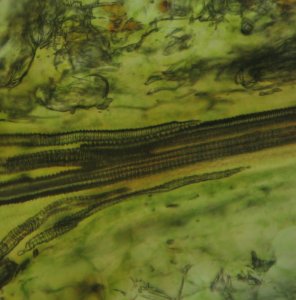
[Figure 1. Spiral Markings on Leaf Veins]
In the case of the watercress leaf veins, its veins are flexible enough to
be manually pulledout into spring like coils, which is visible with low magnification (i.e. 100X.)
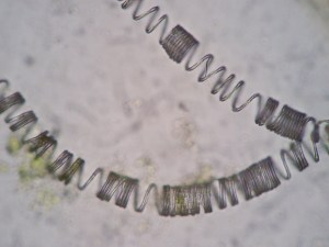
[Figure 2. Unraveled Spring Like Coils of Watercress (100X)]

[Figure 3. Vein CoilsExpanded by Pulling (400x)]
In other leaves like that of spinach, the veins are too rigid to be pull out into a spring like coil. The main vein near the stem of the leaf is formed by a bundle of smaller individual coiled vein tubes. As the main vein progresses towards thetip of the leaf, individual coiled vein tubes branch away from the main vein bundle.
[Figure 4. Main Vein Bundle Branching Off]

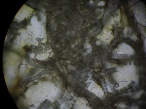
In the case of the watercress, these small-branched veins
form ring like formations further away from the main vein bundle. Veins exhibit two types of coil spacing. One type of veins has tight coils with little spacing between the spiral windings of the coils. The other type has relatively large spacing between the spiral coil windings. Under high magnification (i.e. 400X), the space between the spiral coil windings is filled with a thin sheathing.
[Figure 5. Vein Coil with Sheathing (400X)]
When the watercress vein is pull out to unravel the coil, the thin sheathing tends to break off, although sometimes some fragments of the sheathing still attach to the unraveled coil. The end of the vein coil can form into a pointed spiral tip. Sometimes water in the small veins can be seen draining rapidly out of the vein. The drained small veins form bubbles in the veins, which appear darker under the microscope.
The veins in the meat of the watermelon show coiled spiral structures similar to leaf veins.
[Figure 6. Watermelon Meat Veins with Spiral Markings (400X)]
Discussion:
Leaf veins, and fruit veins appear to be constructed of coils that have thin sheaths covering the spaces between coil windings. Similar sheath covered coils are used in the engineering world for flexible ducting. For example, a portable inside the room air conditioner uses such slinky ® like ducting to connect the hot air exhaust to the window.
[Figure 7. Man-made Coiled Duct]
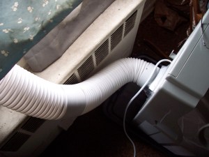
The duct can be compressed into a short length during shipment, and pulled to many times its compressed length for use. It is flexible. It is very light in weight, and yet fairly strong in maintaining its tubular shape. Relatively little material is used to construct such a tube, as compared to a solid pipe, or duct. It is easy to make using linear wire coils. These advantageous characteristics of linearity, of lightweight, of strength to maintain tube shape, of flexibility, of variability of coil winding spacing, and expandability are utilized by the plant in its need to overcome gravity. Different plants may be using varying degrees of these vein coil characteristics to shape its particular needs. It is to be determined how if any of these coil properties can effect the physical shape of the plant such as whether coil rigidity effects the branching angle. While all plants utilize the coil structure for their leaf veins, whether animal blood vessels also utilize coil structuresremains to be determined.
30 Saturday May 2015
Tags
Maximum putter face angle deviation from squared to the putting line for a straight putt can be calculated as the ArcTangent of the radius of the golf hole divided by the length of the straight putt:
Face Angle Deviation from Square in Degrees = ARCTAN(radius of golf hole/length of putt)
The radius of the golf hole can be approximated as 2 inches.
For a 10 feet (120 inches) straight putt, the maximum theoretical putter face angle error (deviation) from being perfectly squared at the moment of impact is:
arctan(2/120) = arctan(0.0167)= 0.96 degrees
The following table lists allowable deviation of putter face angles for straight putts for putting lengths from 5 feet to 30 feet:
Table of Maximum Putter Face Angle Deviation from Square for Medium Length Straight Putts on Flat Surfaces:
5 feet: 2 degrees max face angle error allowed
10 feet: 1 degree
15 feet: 0.64 degree
20 feet: 0.48 degree
25 feet:0.38 degree
30 feet:0.32 degree
For 10 feet straight putts, the putter face angle should be no more than 1 degree off from being perfected squared at the moment of impact.
For 20 feet straight putts, the putter face angle should be no more that half a degree off.
